
Page 238 - 48Fundamentals of Compressible Fluid Mechanics
P. 238
200CHAPTER 12. EVACUATING/FILING CHAMBERS UNDER EXTERNAL VOLUME CONTROL
12.1.1 Rapid Process
Clearly under the assumption of rapid process the heat transfer can be neglected
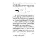
and Fanno flow can be assumed for the tube. The first approximation isotropic
process describe the process inside the cylinder (see figure 12.1.
isontropic process 1 2
Fanno model
Fig. 12.1: The control volume of the “Cylinder”
Before introducing the steps of the analysis, it is noteworthy to think about
the process in qualitative terms. The replacing incompressible liquid enter in the
same amount as replaced incompressible liquid. But in a compressible substance
the situation can be totally different, it is possible to obtain a situation where that
most of the liquid entered the chamber and yet most of the replaced gas can be
still be in the chamber. Obtaining conditions where the volume of displacing liquid
is equal to the displaced liquid are called the critical conditions. These critical con-
ditions are very significant that they provide guidelines for the design of processes.
Obviously, the best ventilation is achieved with a large tube or area. In
manufacture processes to minimize cost and the secondary machining such as
trimming and other issues the exit area or tube has to be narrow as possible. In the
exhaust system cost of large exhaust valve increase with the size and in addition
2
reduces the strength with the size of valve . For these reasons the optimum size
is desired. The conflicting requirements suggest an optimum area, which is also
indicated by experimental studies and utilized by practiced engineers.
The purpose of this analysis to yields a formula for critical/optimum vent
area in a simple form is one of the objectives of this section. The second objective
is to provide a tool to “combine” the actual tube with the resistance in the tube,
thus, eliminating the need for calculations of the gas flow in the tube to minimize
the numerical calculations.
A linear function is the simplest model that decibels changes the volume.
In reality, in some situations like die casting this description is appropriate. Nev-
ertheless, this model can be extended numerical in cases where more complex
function is applied.
(12.1)
*
2 After certain sizes, the possibility of crack increases. * N ?PO
E
*